Arduino Circuit Design Program
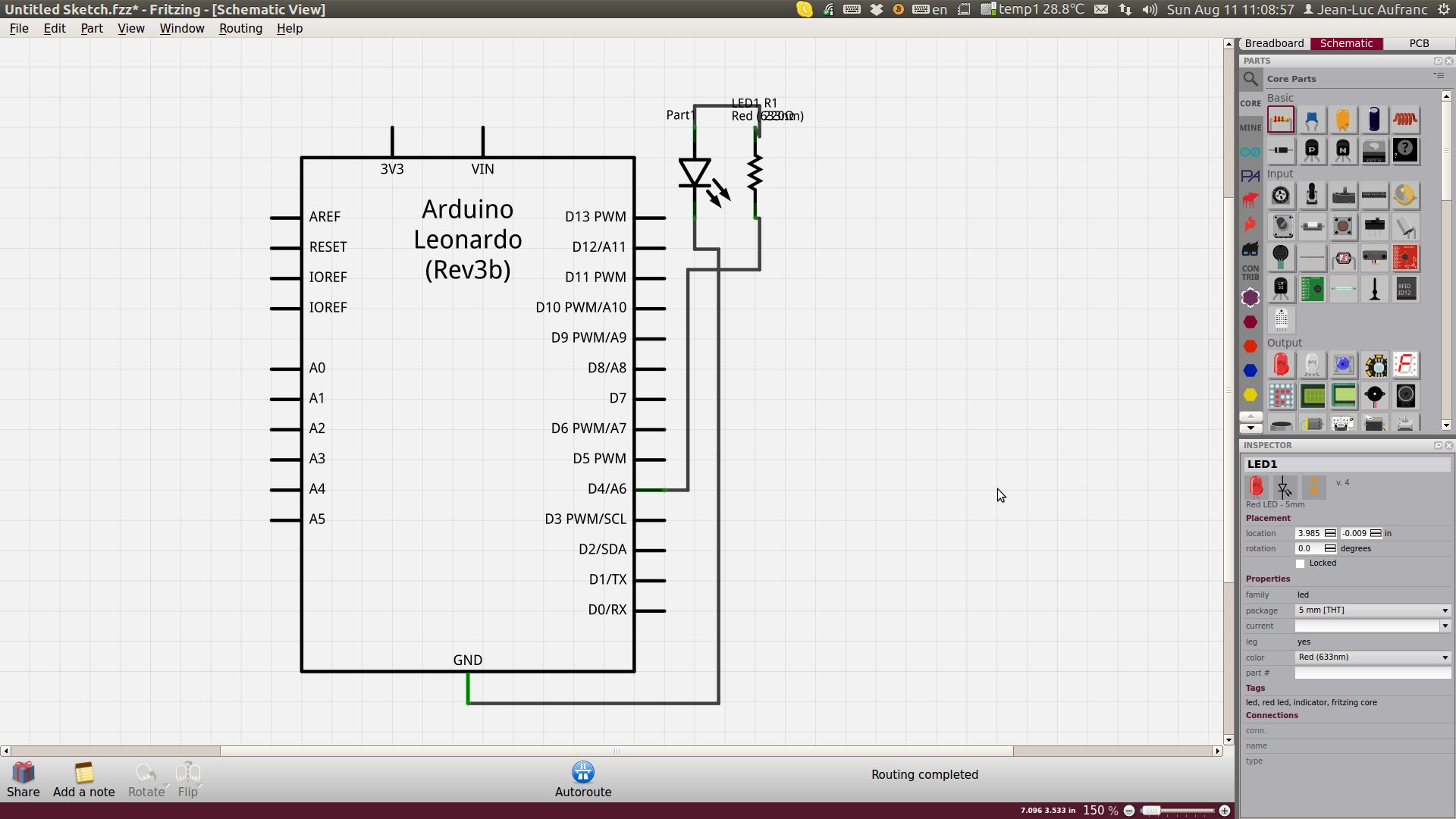
A) Fritzing: Fritzing is an open-source hardware initiative that makes electronics accessible as a creative material for anyone. We offer a software tool, a community website and services in the spirit of Processing and Arduino, fostering a creative ecosystem that allows users to document their prototypes, share them with others, teach electronics in a classroom, and layout and manufacture professional pcbs & Fritzing is essentially an Electronic Design Automation software with a low entry barrier, suited for the needs of designers and artists. It uses the metaphor of the breadboard, so that it is easy to transfer your hardware sketch to the software. From there it is possible to create PCB layouts for turning it into a robust PCB yourself or by help of a manufacturer. Download and Start Download our released on April 3, 2015 and start right away.
Produce your own board With you can easily and inexpensively turn your circuit into a real, custom-made PCB. Try it out now! GameCube.
Autodesk Circuits empowers. Experienced users can skip ahead and go straight to PCB Design. Learning to code is so much cooler when you can program. In this tutorial, you'll learn about some basic electronic circuits and how to connect them to the Arduino board. Breadboard [photo of breadboard]. A) Fritzing: Fritzing is an open-source hardware initiative that makes electronics accessible as a creative material for anyone. We offer a software tool.
B) Qucs: What’s Qucs? Qucs stands for Quite Universal Circuit Simulator. So far Qucs is not yet finished, but it is already packed with features. Take a look at the to get a feel for what it can do.
Qucs is an integrated circuit simulator which means you are able to setup a circuit with a graphical user interface (GUI) and simulate the large-signal, small-signal and noise behaviour of the circuit. After that simulation has finished you can view the simulation results on a presentation page or window. Qucs, briefly for Quite Universal Circuit Simulator, is a circuit simulator with graphical user interface (GUI).
Arduino Circuit Design Program
The GUI is based on Qt® by ®. The software aims to support all kinds of circuit simulation types, e.g. DC, AC, S-parameter, Harmonic Balance analysis, noise analysis, etc.

Qucsator, the simulation backend, is a command line circuit simulator. It takes a network list in a certain format as input and outputs a Qucs dataset. It has been programmed for usage in the Qucs project but may also be used by other applications.
The Qucs GUI is well advanced and allows setting up schematics and presenting simulation results in various types of diagrams. DC, AC, S-parameter, noise and transient analysis is possible, mathematical equations and use of a subcircuit hierarchy (with parameterised subcircuits) are available.
Qucs can also import existing SPICE models for use in your simulations. While Qucs is well developed, we still strive to improve the project, and will always welcome offers of help. Qucs doesn’t just need help with programming, it also needs graphics, high quality example schematics, tutorials for the website and lots more. Qucs comes with a huge array of components and models including HICUM, BSIM2, BSIM3, and soon BSIM6. It also provides many semiconductor based components and models such as OpAmps, Diodes, MOSFETs, PMOSFETs and many more. Some example schematics can be found which demonstrate some of the abilities of Qucs, and many more examples are provided with the program.
Operating Systems Qucs is currently developed under the GNU/Linux OS using the standard autotools with no special effort to support other operating systems. However Qucs is said to be successfully compiled and run on Windows, Solaris, NetBSD, FreeBSD, MacOS, and Cygwin help is needed! License Qucs is released under the GPL license and so it is free for free programmers and users!
Reference Qt® is a registered trademark of Digia. Latest stable release of Qucs: 0.0.18 C) Proteus for Arduino: Proteus VSM for Arduino™ AVR® provides an integrated environment for development, testing and virtually prototyping your embedded system designs based around the popular Arduino™ platform. The unique nature of schematic based microcontroller simulation with Proteus, together with use of schematic snippets as shields or breakout boards makes it fast and fun to experiment with all things Arduino™. Watch the tutorial movie to the right or read on for more detail and purchasing information. Over 35 popular shields and breakout boards now included as standard.
Hundreds of dollars worth of virtual hardware covering everything from leds and lcds to motors and sensors, from SD cards to full ethernet connectivity. See the full list at the bottom of the page. How Does it Work? Proteus VSM for Arduino AVR combines the Proteus VSM technology for embedded simulation with the Arduino toolchain to form a seamless development environment. Arduino shields are represented as project clips in Proteus to simplify the design process.
You can wire on instrumentation (e.g Scopes, Protocol Analysers) or even create your own shields with custom circuitry and driver code. Meanwhile the integrated VSM Studio IDE can automatically handle the download, install and configuration of the Arduino toolchain. At a press of a button, it can then program the processor on the schematic for simulation and debug or the physical Arduino hardware for real world analysis. D) LTspice IV LTspice IV is a high performance SPICE simulator, schematic capture and waveform viewer with enhancements and models for easing the simulation of switching regulators.
Arduino Circuit Diagram Software
Our enhancements to SPICE have made simulating switching regulators extremely fast compared to normal SPICE simulators, allowing the user to view waveforms for most switching regulators in just a few minutes. Included in this download are LTspice IV, Macro Models for 80% of Linear Technology’s switching regulators, over 200 op amp models, as well as resistors, transistors and MOSFET models. (Updated February 1, 2016 ).